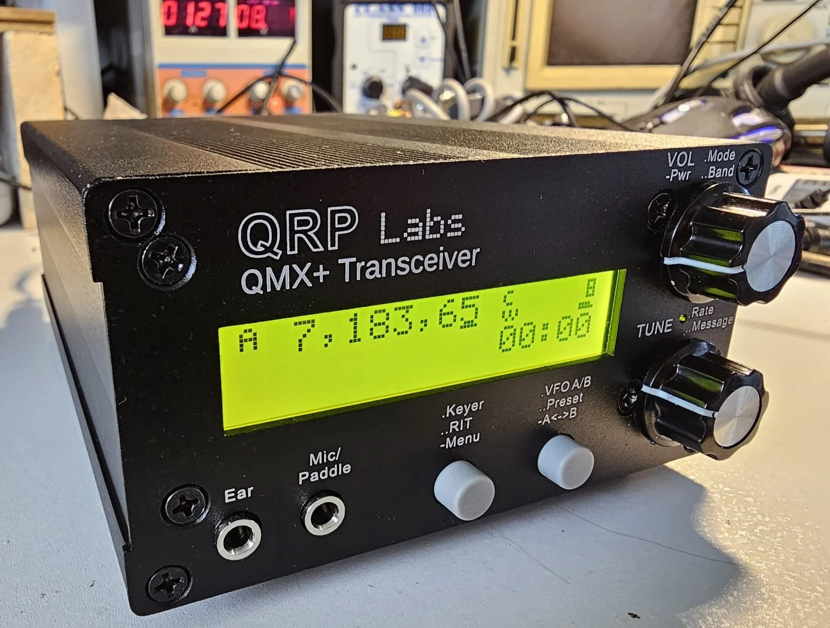

QMX+ 160–6 m Multi‑Mode Transceiver
From unboxing to first QSO – a builder‑friendly step‑by‑step guide
1. Pre‑flight checklist
| Category | What you need | Notes |
|---|---|---|
| Documents | Latest assembly manual for your PCB revision (e.g. Rev 3 doc 3.05) and matching operating manual | Download from the QRP‑Labs QMX+ product page. |
| Tools | 25–30 W temperature‑controlled iron, flux pen, solder wick, fine side‑cutters, tweezers, #1 Phillips, TORX T6, ESD strap, magnifier, bright lighting | Six‑layer board & large ground planes need extra heat – plan accordingly. |
| Test gear | Current‑limited bench PSU (12 V / 1 A), DMM, 50 Ω dummy load, watt‑meter or RF power probe, frequency counter or calibrated SDR, USB‑C cable | Optional: oscilloscope or spectrum analyser for PA check‑out. |
| Consumables | 60/40 or Sn‑Ag‑Cu 0.7 mm solder, isopropyl alcohol, cotton buds | Keep the board squeaky‑clean as you build. |
Before you heat the iron:
- Clear a static‑safe bench and brew decaf – shaky hands ≠ happy solder.
- Inventory every part against the BoM; contact QRP‑Labs immediately if anything’s missing.
- Read the manual twice, then watch a build video or two for extra context.
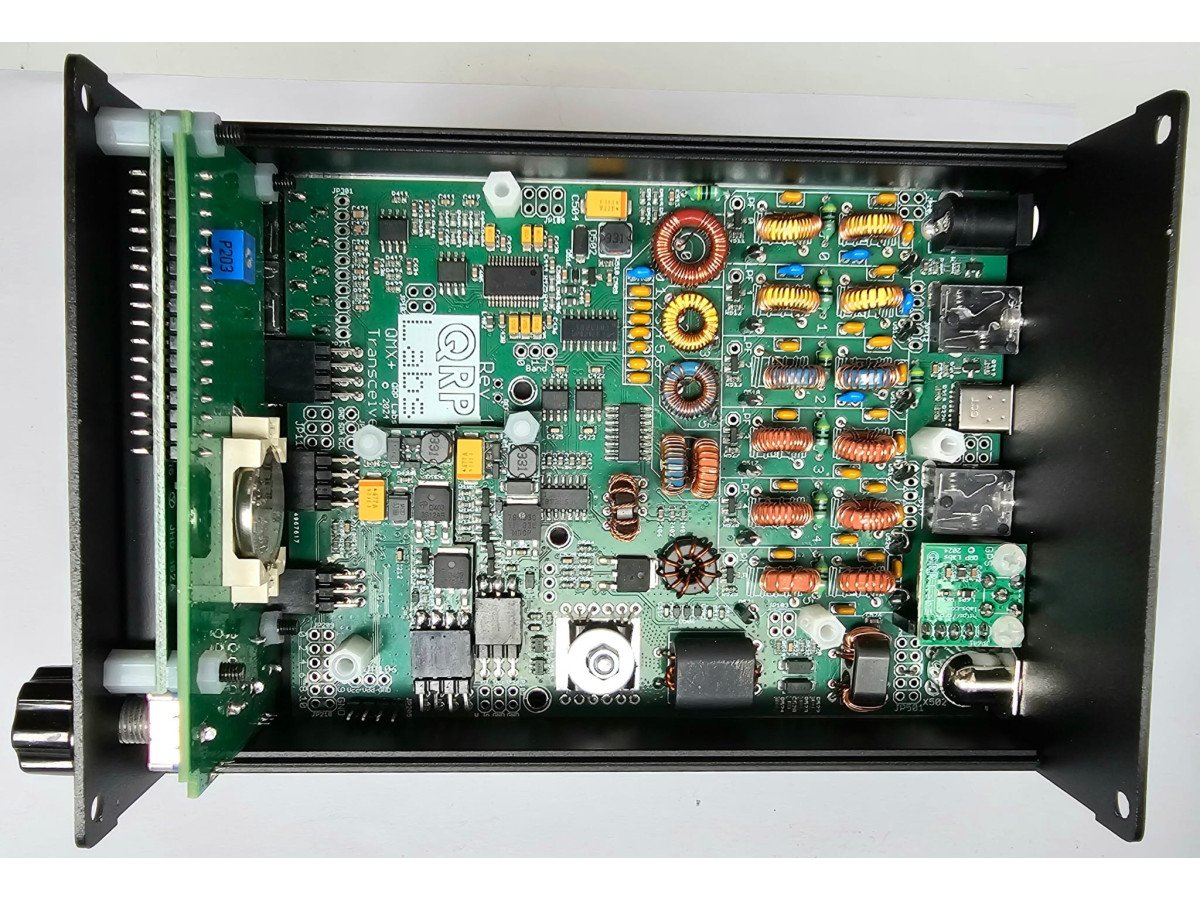
2. Board‑level assembly (main PCB)
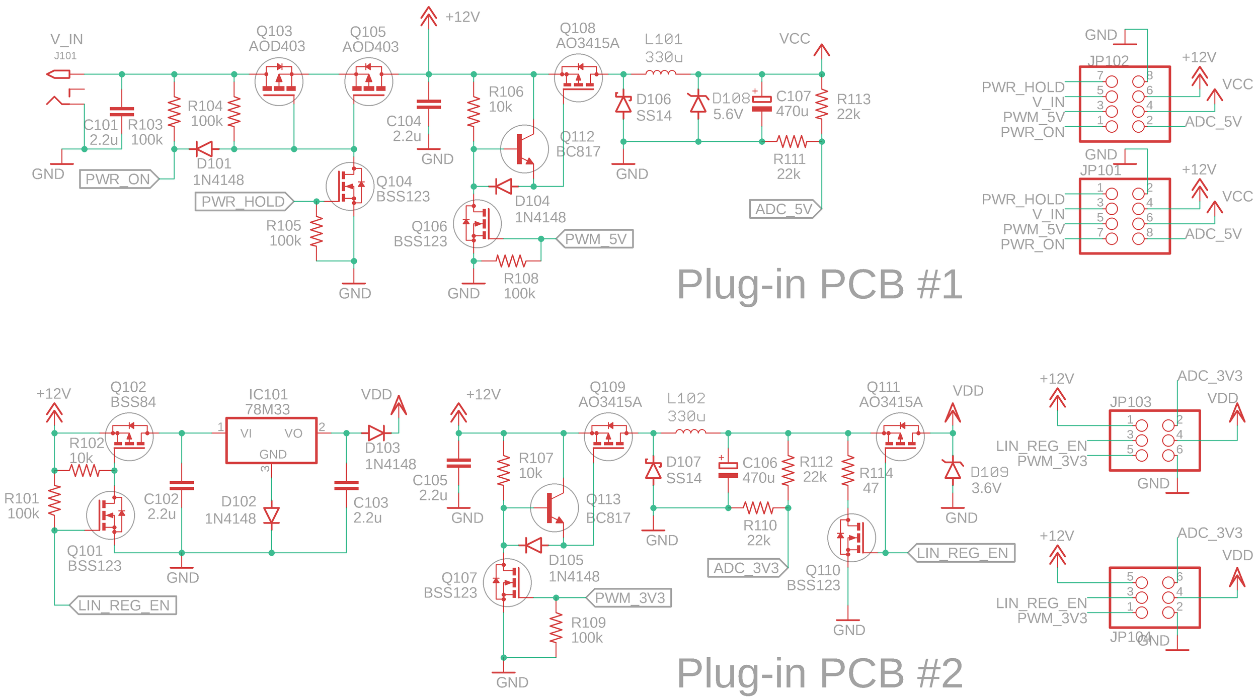
- SMPS daughter‑boards – align headers perfectly; re‑flow any dull factory joints.
- Low‑profile through‑hole parts – resistors, small caps, diodes. Work left‑to‑right, top‑to‑bottom.
- Toroids & transformers
- Wind exactly to the turn count in the manual; keep turns tight and evenly spaced.
Strip enamelby dragging the wire through a molten solder blob before inserting – guaranteed bright copper every time.- Verify continuity with your DMM.
- Power‑train devices (MOSFETs, regulators) and all IC sockets.
- Heat‑sensitive parts last – crystals, TCXO, microphone capsule (if fitted).
The six‑layer PCB soaks heat. Builders report best results with a slightly larger chisel tip, plenty of flux and quick, decisive soldering. Wick excess solder before adding the next part.
3. Front panel & LCD
- Tack‑solder the 16‑pin LCD header, plug the LCD in dry and verify it sits perfectly flush; then complete the joints.
- Install encoders, push‑buttons and 3.5 mm jacks on the front side only – double‑check orientation; mis‑placing them is the #1 de‑soldering horror story.
- Thread the front‑panel PCB onto its spacers and tighten just finger‑snug; you’ll remove it again for cleaning.
4. First power‑up & firmware flash
- Set your PSU to 12 V, 0.5 A current‑limit.
- Hold the left encoder shaft while applying power; the LCD backlight should come up and the current settle around 80 mA RX.
- On first boot choose
QMX + 160–6 mso the MCU loads correct band data. - Connect USB‑C to your PC, run
qld‑flash(Windows/macOS/Linux) and load the latest firmware (≥ 1_02_002). Progress appears on the GUI; the rig reboots automatically.
5. Alignment & self‑test
| Step | What to do | Expected outcome |
|---|---|---|
| REFCAL | Menu → Tests → Cal TCXO → zero‑beat WWV 10 MHz or use the optional GPS module | Reading within ±0.5 Hz |
| PA bias | Menu → Tests → Bias adjust; set each band for 0.22 A at key‑down | 3–5 W into dummy load |
| Band sweep | Use the built‑in signal generator; monitor on a separate receiver | Spurs ≤ –50 dBc |
| SWR bridge | TX into 50 Ω load; SWR should read ≈ 1 : 1 | Confirms bridge wiring |
6. Button up the enclosure
- Clean the board with IPA, blow‑dry, then mount the chassis rails.
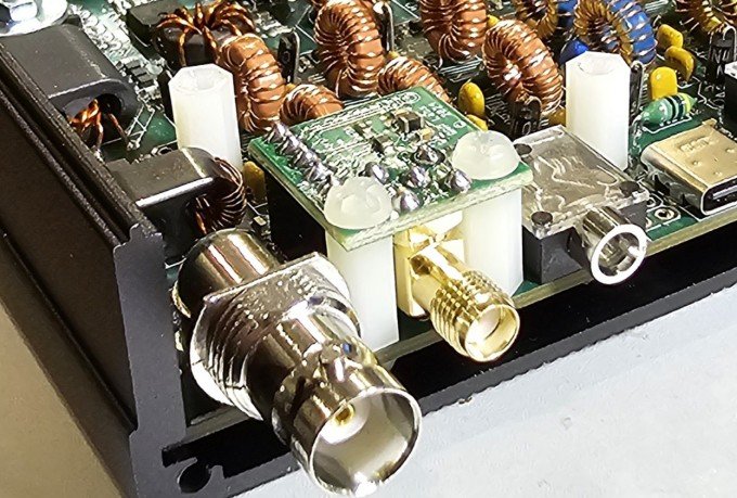
- Slide the PCB into the extruded case; use nylon washers under the BNC and GPS SMA to avoid scratching the panel.
- Install the dev‑board or QLG3 GPS now if you ordered them.
7. Getting on the air
- CW / keyer – internal iambic keyer with memories; menu‑select paddle or straight key.
- Digital – one USB cable to WSJT‑X/JS8Call/etc. Choose the built‑in sound card, set CAT to Kenwood TS‑480, 115 200 baud.
- (Soon) SSB – firmware 1_03 adds full voice‑mode with CESSB processing; mic plugs into front‑panel 3.5 mm TRRS.
8. Popular mods & extras
| Mod | Parts | Why / when |
|---|---|---|
| Internal 3 S 18650 pack & BMS | 3 × 18650, TP4056‑3S | 11 V rail = full 5 W portable; fits behind LCD. |
| ATU‑10 nano | ATU‑10 kit + ribbon | Slips into spare volume; use AUX PTT line. |
| Fan bracket | 40 mm whisper fan | Keeps PA cool on FT8 marathons. |
9. Troubleshooting cheat‑sheet
No LCD backlight
- Missed 12 V rail or reversed LCD header
- Verify +12 V on pin 2 of LCD
High TX current, < 1 W out
- Toroid leads not fully stripped or PA bias mis‑adjusted
- Re‑strip leads and realign bias
USB not recognised
- Solder bridge on MCU header
- Inspect under magnification and continuity‑test adjacent pins
Still stumped? Search the QRPLabs@groups.io archive – hundreds of builders have logged their fixes.
10. Final sanity & safety
- Always TX only into a 50 Ω load or tuned antenna.
- RF burns hurt – the PA heat‑spreader can reach 70 °C at full duty.
- Obey your local licence conditions; 5 W is QRP, but it can still cause interference.